Meshtastic is being used in the Palo Alto AREDN system to provide broad coverage for short messages. Much has been written about Meshtastic, and the interested reader should Google for Meshtastic and/or peruse YouTube for background material.
In the Palo Alto AREDN system, Meshtastic gateways are linked together over AREDN and share data via our MQTT broker.
Palo Alto ESVs can participate in our Meshtastic network by carrying a Meshtastic client device and/or installing a gateway at their QTH.
Materials
Links to Amazon are affiliate links. I earn a microscopic commission. Your price is exactly the same.
- Raspberry Pi 1 GB 3B+ https://amzn.to/3PsUKXW
- Weatherproof Wall-Mount Enclosure https://amzn.to/3NjbTTg
- OPTIONAL pole-mounting kit for the enclosure https://amzn.to/46Wk8eS
- Sandisk Extreme Pro MicroSD card https://amzn.to/4rqaMzt
- MicroSD adapter that fits your computer (varies by model -- you will have to figure this out). Some computers have built-in SD card slots, and you will only need a MicroSD-to-SD adapter. Some computers don't have these. In that case, you will need a USB-A or USB-C MicroSD adapter, whichever fits your computer.
- PoE Splitter (Note: to mate with the PI 3B+, the splitter MUST have a micro-USB connector, not USB-C). This splitter is 802.3af (NOT Passive PoE) https://amzn.to/4sAFXZI
- 802.3af (PoE+) PoE injector -- many choices https://amzn.to/4rVeJgo You can also use a PoE+ network switch for this purpose, if you have one. Don't try to use a passive PoE port to power the Gateway. It won't work and may cause damage.
- Adafruit RFM95W 915 MHZ Bonnet https://www.adafruit.com/product/4074?srsltid=AfmBOoq96FWFypctpNP8o__HGTWKulOFdQltQIxS6qObMpxZSqbcSlpi
- M20 RJ45 Ethernet pigtail (mine has blue wire, YMMV) https://amzn.to/4bva92F
- SMA Male to Type N pigtail https://amzn.to/4ujNZYH Important note: this will require some soldering skill to remove the u.FL connector from the Adafruit board and replace it with an SMA connector:
- SMA edge-mount female connector https://amzn.to/4rhRn3r
- If you do not want to solder, then you should order a u.FL to Type N pigtail https://amzn.to/4bBVkLC instead of the above SMA Male to Type N Pigtail and skip the SMA edge-mount female connector entirely.
- M2.5 Brass Male-Female Hex Standoffs Spacers Screws Nuts Flat Washers Assortment https://amzn.to/3N6OwMR
- 6" Zip ties https://amzn.to/3NgYE5x
- GE Silicone adhesive https://amzn.to/4s85h9M
- 900 MHz vertical omnidirectional antenna, Type N connector. Many options. It is important to choose an antenna that is specifically designed for outdoor operation, and high outdoor mounting provides the best gain. Here are a few choices:
- Type N to Type N LMR400 cable -- Mounting the enclosure near the antenna allows for the shortest cable run. This is a 5' cable: https://www.l-com.com/coaxial-n-male-to-n-male-400-ultra-flex-series-assembly-50-ft
- Coax-attached surge protector here This needs to be connected to a solid ground to provide protection.
- Ethernet-attached surge protector https://amzn.to/4b3YCY5 This, too, needs to be connected to a solid ground.
- Self amalgamating tape https://amzn.to/3OYBTEg
- Vent plug, Amphenol here
- Vent plug brass nut here
- Two ethernet cables -- one from your hAP to the PoE injector and one from the PoE injector to the Meshtastic gateway you will construct
Tools
You will need a few basic hand tools including small screwdrivers (including a Philips eyeglass-screw size driver), needle-nose pliers, diagonal cutters, an electric drill and bits. If you have a "Unibit" step drill bit, it will make drilling the large holes easy.
Note: You will be handling circuit boards that are static sensitive. They only require a reasonable level of care. Boards are safe while they are in their static-shielding bags. When removing boards from their bags and handling them, take care to prevent static discharge damage. It is recommended that you do your handling of circuit boards on a conductive working surface like a cookie sheet. Place the boards in their static-shielding bags on the surface. Touch the working surface with your finger before removing the boards from their static-shielding bags.
Note: The LoRa board is a radio transceiver. As with ANY transmitter, never transmit without having a properly-tuned antenna connected. Damage to the transmitter can result in power that is reflected off of an unterminated feed line, even if the "feed line" is a circuit trace. The transmitter produces power, and it has to go someplace. If there's no antenna, the power is reflected back to the transmitter and turns into heat. With enough heat, the transmitter circuit will be destroyed.
Preparation of the MicroSD card
We will use Debian 13 (so-called "Trixie") for the Raspberry 3B+ board.
Install the Raspberry Pi Imager on your computer (Mac, Windows, or Linux) from:
https://www.raspberrypi.com/software
Plug the MicroSD card into your computer using the purchased adapter, then run Raspberry Pi Imager:
- Click Choose Device and select Raspberry Pi 3.
- Click Choose OS, then Raspberry Pi OS (other), then Raspberry Pi OS Lite (64-bit). Verify that the description says Bookworm. Do not select Trixie or any other version — the Meshtastic daemon and its shared libraries require Bookworm.
- Click Choose Storage and select your MicroSD card.
- Click Next. When prompted to customize settings, click Edit Settings.
- In the General tab:
- Set hostname (e.g., yourcallsign-meshtastic-gw)
- Enter a username and password — write these down, you will need them for SSH access
- Set locale to your timezone (e.g., America/Los_Angeles) and keyboard layout us
- Leave WiFi unchecked — the gateway uses Ethernet
- In the Services tab:
- Enable SSH with Use password authentication
- Optionally paste your id_rsa.pub key for passwordless SSH access
- Click Save, then Yes to apply settings, then Yes to confirm writing.
- The imager will write and then verify the data on the card. This takes 2–10 minutes depending on your computer and card speed.
- When complete, click Finish and remove the card.
Set the MicroSD card aside for mechanical assembly.
Mechanical
Backing Board Assembly
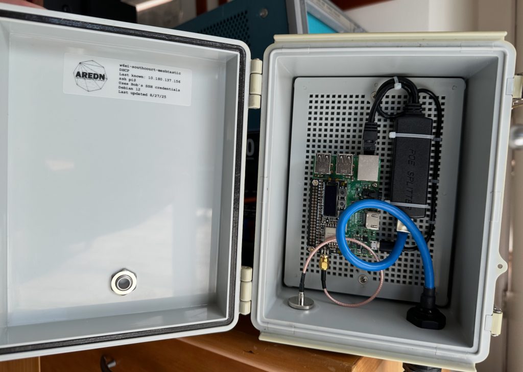
Become familiar with the Pi and the Adafruit board. They will plug together using the 40 pin "header" on the top side of the Pi. Note the position of the Pi's ethernet connector and its Micro USB connector. Compare it to the photo.
We will be using some carefully-chosen screws and standoffs to hold everything together. More on that below.
For reference, the view you see in the photo of the Pi, the Adafruit board and the backing board in the enclosure will be referred to as their "top" sides.
With a Sharpie, mark the top of the backing board. Then, remove the backing board from the enclosure. Put the screws aside.
Note in the photo the placement of the various components and their orientation. By counting holes, you can get a good sense of where each one goes. If you like, mark rectangles on the backing board for the position of the PoE Splitter and the Raspberry Pi. Cable management can be a problem if you don't get the spacing or orientation right, so study the photo.
Find the four mounting holes on the Pi. Two are at board corners and two are not.
Using the Pi as a template, on the top of the backing board, mark and drill holes corresponding to the four holes in the Pi but do not attach the Pi at this time. Note that the holes in the Pi don't line up perfectly with the holes in the backing board. The holes you drill should be just big enough for the body of the screws but not so large that the head of the screw will pull through. Try to use existing holes where possible.
Assembling the Pi and Adafruit boards
You have a choice in how you will attach your Adafruit board to its coaxial cable. The board comes with a u.FL connector (sometimes written as "IPEX"), and you've already chosen (in the Materials list) to either stick with this or replace these with SMA connectors. u.FLs are small and a bit fiddley. Once a u.FL cable is snapped to its u.FL jack, the connection is adequately strong for an in-an-enclosure situation. You should know that u.FLs are designed for only a small number of mate / un-mate cycles (30) over their lifetime, which is fine for this project. Still, some people don't like u.FLs and don't have confidence in them. For those in this category, switch to SMA. I did.
- At an ESD-safe soldering station, and with a small-tipped, ~25 watt soldering iron, remove the u.FL jack from the Adafruit board. It is soldered at three points. A hot air soldering station is preferred for this task, but you can make it work with a soldering iron, Solder Wick, and patience.
- Clean excess solder from the board's solder pads with Solder Wick after removing the u.FL.
- Clean the pads with isopropyl alcohol and a Q-tip.
- Gently press the SMA connector on to the edge of the board, over the pads. Check both sides of the board for proper placement of the connector's tabs.
- Solder the tabs to the pads.
- Clean off the flux with isopropyl alcohol.
Take a look at the standoff kit you purchased. Make sure you orient it properly before opening -- the lid is the "thin" part. You will be using 2.5 mm standoffs. This refers to the diameter of the threaded portion. Note that some standoffs are Female (F-F) on both ends while some are Female on one end and Male (F-M) on the other end. Screws and standoffs come in various lengths.
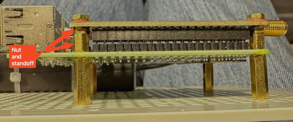
To connect the Adafruit board to the Pi, select standoffs tall enough to prevent the components on the Pi from coming in contact with the underside of the Adafruit board but short enough so that the pins in the 40 pin header are fully mated. Experience shows that a spacing of 7.8 mm is about right. But since that's not a standard size, you will need to use a combination of a nut and a standoff as shown. You will only use two standoffs for the Adafruit board -- at either end of the Pi's 40 pin header.
Note that on Pi 3B+ boards, there is a 4-pin header that will come into contact with the underside of the Adafruit board -- this isn't good. The 4 pins are for an internal USB connection. I cut the pins off. You can desolder the connector if you wish. Either way, you don't want those pins touching the Adafruit board. One of them is +5 volts. Having it contact ground will ruin your day.
Pass the M end of these standoffs through the underside of the Adafruit board, using the holes at either end of the 40 pin connector. Fasten at the top of the Adafruit board using washers and nuts. Use a wrench to tighten, but take care not to strip threads nor cut into the board.
Select two F-M spacers and two same-height F-F spacers to be used on the underside of the Pi to hold it above the backing board. 15 mm is plenty of height. Thread the M end of the F-M spacers through the Pi and into the spacers you just installed on the Adafruit board. Using two short screws, attach the F-F spacers to the other two holes on the opposite edge of the Pi. At this point, you should have four equal-height spacers with F ends on the underside of the Pi.
Making sure to mate the pins correctly, plug the Adafruit board into the Pi's pin header. Press down until the standoffs touch the Pi. Check to make sure the Adafruit board will remain well above the components on the Pi. Do not put screws into the underside of the Pi at this time.
Plug the MicroSD card you prepared above into the bottom of the Pi. Note that the card will only go in one way -- with the gold tabs on the MicroSD card facing the Raspberry Pi board.
Attach the Pi to the backing board with four 2.5 mm screws. Make sure the Pi is oriented correctly and that you are attaching the Pi to the top of the backing board.
Attach the PoE Splitter to the backing board with zip ties. Pull the zip ties tight with needle nose pliers. Trim the zip tie loose ends.
Connect the ethernet cable from the PoE Splitter to the Pi. Connect the Micro USB cable from the Splitter to the Pi.
Using zip ties, secure these wires as shown in the photo. Trim the zip tie loose ends. Set this assembly aside for now.
Enclosure Preparation
Mark and drill holes for the Type N connector and the ethernet pigtail as shown in the photo. Lay the enclosure on its back on your table with the lid up. Looking at the bottom of the enclosure, measure 1" from the left and 1.5" up from the table for the N connector. For the Ethernet (M20) connector, measure 1.25" from the right and 1.5" up from the table. A Unibit or "step drill" of the right size makes short work of this operation. Drill from outside-in.
Mark and drill a hole in the lid of the enclosure for the Amphenol LTW vent plug as shown in the photo. Install it and orient it so the text on the outside will be right-side up when the enclosure is mounted vertically (as shown in the photo). The Amphenol plug is very important. The box heats up during the day and cools down at night. The heating is so intense as to raise the internal pressure of the box, pushing air out past the gaskets in the door. And conversely, when the box cools, the internal pressure goes below ambient, sucking in exterior air past that gasket. This will, over time, suck in moisture and keep it in the box, corroding components. The Amphenol vent allows for pressure relief, and it has a Goretex internal membrane that keeps water from entering.
CLEAN the area in and around the holes you drilled. Use Windex or something similar. A clean surface is necessary for proper adhesion of the silicone sealant.
Attach the Type N pigtail to the enclosure. Use a modest amount of silicone adhesive around the threads where they pass through the enclosure will help to provide waterproofing. A modest amount of silicone, applied properly, will outperform a big glob slathered over the connector. Be careful NOT to get silicone in the part of the threads to which the antenna will attach.
Attach the Ethernet pigtail, again using silicone adhesive. The outer part of the pigtail unscrews to reveal the weatherproof ethernet port. You will be running a wire from the PoE injector's POWER+DATA port to this weatherproof ethernet port later. Take a minute to learn how the weatherproofing nuts and grommets will work with your ethernet cable.
Re-attach the backing board with the Pi and the PoE splitter into the enclosure and fasten with the two screws you removed previously.
Carefully attach the u.FL connector to the Adafruit board.
Attach the Ethernet pigtail's cable to the PoE splitter's input.
With a sharpie, write your name and date on the inside lid of the box.
This completes the mechanical assembly.
Software configuration
Reference: Meshtastic official documentation at https://meshtastic.org/docs/hardware/devices/linux-native-hardware/
Pre-startup checks
- Temporarily connect the vertical antenna to the Type N connector. Take care that the antenna will not put force on the circuit board when it is connected.
- Double-check that the u.FL connector is firmly seated on the Adafruit board. Alternatively, if you have switched to SMA, screw the SMA connector in finger tight.
- Critical: Always verify the antenna is connected before powering the gateway via PoE injector.
Network Connection and Initial Access
- Connect an ethernet cable from a hAP LAN port to the PoE injector DATA port.
- Connect an ethernet cable from the PoE injector POWER+DATA port to the Meshtastic gateway's ethernet port.
- Power the PoE injector on.
- The RED LED on the Pi will light.
- The GREEN LED will flicker as the device boots.
- Find the gateway's IP address in the hAP admin page under the LAN DHCP section. Look for the hostname you chose during MicroSD preparation. SSH in:
ssh yourusername@10.x.x.xIf you added your id_rsa.pub during MicroSD preparation, no password will be needed.
Install meshtasticd (Meshtastic daemon)
Run these commands to add the Meshtastic package repository and install the daemon. These commands are for Debian 12 (Bookworm) — if you accidentally installed a different OS version, stop here and re-flash the MicroSD card with Bookworm.
echo 'deb http://download.opensuse.org/repositories/network:/Meshtastic:/beta/Debian_12/ /' | sudo tee /etc/apt/sources.list.d/meshtastic-beta.list

curl -fsSL https://download.opensuse.org/repositories/network:Meshtastic:beta/Debian_12/Release.key | gpg --dearmor | sudo tee /etc/apt/trusted.gpg.d/network_Meshtastic_beta.gpg > /dev/null

sudo apt update

sudo apt install -y meshtasticd
Future firmware updates use sudo apt upgrade meshtasticd.
Deploy the fixed binary
The stock meshtasticd binary has a bug in its BinarySemaphorePosix class: the give() method is a no-op and take() just sleeps without actually synchronizing. This breaks the cooperative thread scheduler — radio RX interrupts are missed, telemetry never transmits over the mesh, and the gateway cannot function as an MQTT relay. A fix has been submitted upstream (meshtastic/firmware PR #9895). Until it is merged into a released version, the stock binary must be replaced with a fixed one.
Into your home directory on the gateway, download and unzip the fixed binary here (current as of March, 2026 -- you might want to check to see if the fix has been incorporated into an official version that is newer). It will download as ~/meshtastic-stripped.zip, and when you unzip it, it will be ~/meshtastic-stripped
Then make a backup copy of the existing meshtasticd and replace it with the fixed binary:
sudo cp /usr/bin/meshtasticd /usr/bin/meshtasticd.orig
sudo cp ~/meshtasticd-stripped /usr/bin/meshtasticd
sudo chmod +x /usr/bin/meshtasticdNote: If the meshtasticd package is later upgraded via apt, it will overwrite the fixed binary. Re-deploy the fixed binary after any package upgrade until the upstream fix is released.
Set up the Raspberry Pi's boot environment
Enable SPI and I2C, and add the spi0-0cs overlay required by the LoRa bonnet. These commands are safe to run on a fresh install — they will not duplicate settings that already exist.
sudo raspi-config nonint set_config_var dtparam=spi on /boot/firmware/config.txt

if ! grep -q '^\s*dtoverlay=spi0-0cs' /boot/firmware/config.txt; then
    sudo sed -i '/^\s*dtparam=spi=on/a dtoverlay=spi0-0cs' /boot/firmware/config.txt
fi

sudo raspi-config nonint set_config_var dtparam=i2c_arm on /boot/firmware/config.txtSet Up LoRa Board Configuration File
Copy the Adafruit radio bonnet configuration to the Meshtastic config directory:
sudo cp /etc/meshtasticd/available.d/lora-Adafruit-RFM9x.yaml /etc/meshtasticd/config.d/Enable the web server
Edit the Meshtastic configuration file:
sudo nano /etc/meshtasticd/config.yamlScroll down (Ctrl-V) to find the Webserver section. Uncomment and set these lines (note the two leading spaces are required):
  Port: 443
RootPath: /usr/share/meshtasticd/webThen save and exit nano by typing control-O (save) and then control-X (exit)
Reboot your Pi at this point
sudo rebootWait about a minute, then SSH back in.
Start meshtasticd
Enable the daemon to start automatically on boot, start it now, and verify it is running:
sudo systemctl enable meshtasticd
sudo systemctl start meshtasticd
sudo systemctl status meshtasticdYou should see active (running) in the output. To view the live log:
sudo journalctl -f -u meshtasticdLook for RF95 init result 0 and RF95 init success to confirm the LoRa radio initialized. Exit the log viewer with Ctrl-C.
Install Python Configuration Tools
Set up a Python virtual environment with the Meshtastic command-line tools:
cd ~
python3 -m venv ~/venv
source ~/venv/bin/activate

pip3 install --upgrade pytap2
pip3 install --upgrade "meshtastic[cli]"Important: You must run source ~/venv/bin/activate in each new SSH session before using the meshtastic command.
Configure the Gateway (Palo Alto settings)
Run the following commands to configure the radio, MQTT, and network settings. Contact Bob W6EI for the channel PSK (<key>) and MQTT credentials (<mqtt_username> and <mqtt_password>).
Set the node identity (replace with your node name and 4-character short name):
meshtastic --host localhost --set-owner 'Your Node Name'
meshtastic --host localhost --set-owner-short 'ABCD'Configure the LoRa radio:
meshtastic --host localhost --set lora.region US
meshtastic --host localhost --set lora.use_preset true
meshtastic --host localhost --set lora.modem_preset LONG_MODERATE
meshtastic --host localhost --set lora.channel_num 10
meshtastic --host localhost --set lora.hop_limit 3
meshtastic --host localhost --set lora.tx_enabled true
meshtastic --host localhost --set lora.tx_power 30
meshtastic --host localhost --set lora.config_ok_to_mqtt trueConfigure the channel (PSK from Bob W6EI):
meshtastic --host localhost --ch-set name PaloAltoESV --ch-index 0
meshtastic --host localhost --ch-index 0 --ch-set psk base64:<key>
meshtastic --host localhost --ch-index 0 --ch-set uplink_enabled true
meshtastic --host localhost --ch-index 0 --ch-set downlink_enabled true
Configure MQTT
Each gateway has its own MQTT username and password. Do not reuse credentials from another gateway. Contact the system administrator for this gateway's specific credentials.
meshtastic --host localhost --set mqtt.enabled true --set mqtt.address 10.0.224.73 --set mqtt.root es/gw/<node_hex_id> --set mqtt.encryption_enabled false --set mqtt.json_enabled false

meshtastic --host localhost --set mqtt.username '<mqtt_username>' --set mqtt.password '<mqtt_password>'where is the gateway's Meshtastic node ID in hex (e.g., es/gw/eb088ec7). To find the node ID, run meshtastic --host localhost --info and look for the node number, then convert to hex. Themqtt.root field is limited to 32 characters — longer values are silently rejected.
Important: mqtt.username and mqtt.password must be set on the same command line (as shown above) or the values may be silently ignored. After reboot, always verify credentials persisted:
meshtastic --host localhost --get mqtt.usernameConfigure device and network settings:
meshtastic --host localhost --set device.role CLIENT
meshtastic --host localhost --set device.node_info_broadcast_secs 3600
meshtastic --host localhost --set device.rebroadcast_mode ALL
meshtastic --host localhost --set device.tzdef America/Los_Angeles

meshtastic --host localhost --set power.is_power_saving false

meshtastic --host localhost --set network.eth_enabled true
meshtastic --host localhost --set network.ntp_server w6ei-ntp.local.meshReboot to apply all settings:
meshtastic --rebootVerify the Configuration
After the reboot, SSH back in, activate the Python environment, and verify:
source ~/venv/bin/activate

meshtastic --host localhost --get lora.region
meshtastic --host localhost --get mqtt.username
meshtastic --host localhost --get mqtt.password
meshtastic --host localhost --get mqtt.rootlora.region should return 1 (US region). Verify other settings match expected values after reboot. MQTT settings can silently revert if not set correctly.
Check the log for successful radio initialization and MQTT connection:
sudo journalctl -u meshtasticd --since '2 min ago' --no-pager | grep -E 'RF95 init|Frequency set|Bandwidth set|MQTT'Expected output includes:
RF95 init result 0
RF95 init success
Frequency set to 903.187500
Bandwidth set to 125.000000For a full configuration dump:
meshtastic --host localhost --export-configInstallation
The enclosure and antenna can be mounted indoors (e.g., in an attic) or outdoors using an optional pole mount. Choosing the mounting location and designing the means to make it secure are beyond the scope of this tutorial. Outdoor installation brings many additional considerations.
The responsibilities of proper installation are solely yours.
As you create your own installation plan, here are some things worth considering:
- Height is Might: one of the cardinal rules of RF propagation. The higher your antenna, the better your propagation will be. But this immediately raises a number of other considerations.
- How far can I separate the antenna from the enclosure? Preferably, you will mount the enclosure and the antenna together at the high point. This minimizes feedline (coax) losses, but it also introduces challenges in getting to the enclosure, should you need to service the equipment inside. In general, you should keep the feedline short -- 5 feet or less is a good choice for this gateway -- and rely on the ethernet cable to cover the distances involved. Good quality Cat6 ethernet allows for distances up to 100 meters, which should be sufficient for most home installations. We recommend UV-protected ethernet cable. The other kind will get crispy in a few years and will fail.
- How do I protect against lightning? Again, this is a subject far beyond the scope of this tutorial. Every ham should already be familiar with the basics of antenna grounding best practices. The ARRL has a number of publications that are intended to help. See this web page to get started. It is important to know that there is no such thing as lightning protection in the absolute sense. Where lightning will strike depends on many factors, and no amount of "lightning arresters" will actually arrest lightning. Good practice involves thoughtful placement, proper grounding, and surge suppression (for both the coax and the ethernet cable).
- Plan for the wind. On this website there are some guidelines for wind loading calculations (this page). We recommend you read them and plan accordingly. This is especially important for installations on or near hilltops where winds can be high during storms.
- Water is amazing. Even with very careful design and construction, accept that if water can get into your enclosure, it will. Use silicone to seal the holes you drilled. Use self-amalgamating tape over all coax connections exposed to the elements.
- No enclosure lasts forever. The gasket on the enclosure's door will deteriorate over time, leading to accelerating ingress of moisture. The plastic box will degrade. A five year lifetime is a good guess. Plan to inspect the enclosure annually.
Reference
The final Meshtastic board configuration, as dumped:
(venv) $ meshtastic --tcp --info   # just an example...
Connected to radio

Owner: Meshtastic 8ec7 (8ec7)
My info: { "myNodeNum": xxxxxxxxxx, "minAppVersion": 30200, "pioEnv": "native-tft", "nodedbCount": 1, "rebootCount": 0, "deviceId": "", "firmwareEdition": "VANILLA" }
Metadata: { "firmwareVersion": "2.7.15", "deviceStateVersion": 24, "hasWifi": true, "positionFlags": 811, "hwModel": "PORTDUINO", "hasPKC": true, "excludedModules": 13568, "canShutdown": false, "hasBluetooth": false, "hasEthernet": false, "role": "CLIENT", "hasRemoteHardware": false }

Nodes in mesh: {
  "!eb088ec7": {
    "num": xxxxxxxxxx,
    "user": {
      "id": "!eb088ec7",
      "longName": "Meshtastic yyyy",
      "shortName": "8ec7",
      "macaddr": "aa:bb:cc:dd:ee:ff",
      "hwModel": "PORTDUINO",
      "publicKey": "...",
      "isUnmessagable": false
    },
    "position": {},
    "deviceMetrics": {
      "batteryLevel": 101,
      "voltage": 0.0,
      "channelUtilization": 0.0,
      "airUtilTx": 0.082055554,
      "uptimeSeconds": 795
    },
    "isFavorite": true
  }
}

Preferences: {
  "device": {
    "nodeInfoBroadcastSecs": 3600,
    "tzdef": "America/Los_Angeles",
    "role": "CLIENT",
    "serialEnabled": false,
    "buttonGpio": 0,
    "buzzerGpio": 0,
    "rebroadcastMode": "ALL",
    "doubleTapAsButtonPress": false,
    "isManaged": false,
    "disableTripleClick": false,
    "ledHeartbeatDisabled": false,
    "buzzerMode": "ALL_ENABLED"
  },
  "position": {
    "positionBroadcastSecs": 900,
    "positionBroadcastSmartEnabled": true,
    "gpsUpdateInterval": 120,
    "positionFlags": 811,
    "broadcastSmartMinimumDistance": 100,
    "broadcastSmartMinimumIntervalSecs": 30,
    "gpsMode": "NOT_PRESENT",
    "fixedPosition": false,
    "gpsEnabled": false,
    "gpsAttemptTime": 0,
    "rxGpio": 0,
    "txGpio": 0,
    "gpsEnGpio": 0
  },
  "power": {
    "waitBluetoothSecs": 60,
    "sdsSecs": 4294967295,
    "lsSecs": 300,
    "minWakeSecs": 10,
    "isPowerSaving": false,
    "onBatteryShutdownAfterSecs": 0,
    "adcMultiplierOverride": 0.0,
    "deviceBatteryInaAddress": 0,
    "powermonEnables": "0"
  },
  "network": {
    "ntpServer": "xxx",
    "ethEnabled": true,
    "wifiEnabled": false,
    "wifiSsid": "",
    "wifiPsk": "",
    "addressMode": "DHCP",
    "rsyslogServer": "",
    "enabledProtocols": 0,
    "ipv6Enabled": false
  },
  "display": {
    "screenOnSecs": 600,
    "displaymode": "COLOR",
    "gpsFormat": "UNUSED",
    "autoScreenCarouselSecs": 0,
    "compassNorthTop": false,
    "flipScreen": false,
    "units": "METRIC",
    "oled": "OLED_AUTO",
    "headingBold": false,
    "wakeOnTapOrMotion": false,
    "compassOrientation": "DEGREES_0",
    "use12hClock": false,
    "useLongNodeName": false
  },
  "lora": {
    "usePreset": true,
    "modemPreset": "LONG_MODERATE",
    "bandwidth": 250,
    "spreadFactor": 11,
    "codingRate": 5,
    "region": "US",
    "hopLimit": 3,
    "txEnabled": true,
    "txPower": 30,
    "channelNum": 10,
    "sx126xRxBoostedGain": true,
    "configOkToMqtt": true,
    "frequencyOffset": 0.0,
    "overrideDutyCycle": false,
    "overrideFrequency": 0.0,
    "paFanDisabled": false,
    "ignoreIncoming": [],
    "ignoreMqtt": false
  },
  "bluetooth": {
    "enabled": true,
    "mode": "FIXED_PIN",
    "fixedPin": 123456
  },
  "security": {
    "publicKey": "...",
    "privateKey": "...",
    "serialEnabled": true,
    "adminKey": [],
    "isManaged": false,
    "debugLogApiEnabled": false,
    "adminChannelEnabled": false
  },
  "version": 0
}

Module preferences: {
  "mqtt": {
    "enabled": true,
    "address": "xxx",
    "root": "meshtastic/xxx",
    "username": "",
    "password": "",
    "encryptionEnabled": false,
    "jsonEnabled": false,
    "tlsEnabled": false,
    "proxyToClientEnabled": false,
    "mapReportingEnabled": false
  },
  "serial": {
    "enabled": false,
    "echo": false,
    "rxd": 0,
    "txd": 0,
    "baud": "BAUD_DEFAULT",
    "timeout": 0,
    "mode": "DEFAULT",
    "overrideConsoleSerialPort": false
  },
  "externalNotification": {
    "enabled": false,
    "outputMs": 0,
    "output": 0,
    "outputVibra": 0,
    "outputBuzzer": 0,
    "active": false,
    "alertMessage": false,
    "alertMessageVibra": false,
    "alertMessageBuzzer": false,
    "alertBell": false,
    "alertBellVibra": false,
    "alertBellBuzzer": false,
    "usePwm": false,
    "nagTimeout": 0,
    "useI2sAsBuzzer": false
  },
  "storeForward": {
    "enabled": false,
    "heartbeat": false,
    "records": 0,
    "historyReturnMax": 0,
    "historyReturnWindow": 0,
    "isServer": false
  },
  "rangeTest": {
    "enabled": false,
    "sender": 0,
    "save": false,
    "clearOnReboot": false
  },
  "telemetry": {
    "deviceUpdateInterval": 2147483647,
    "environmentUpdateInterval": 0,
    "environmentMeasurementEnabled": false,
    "environmentScreenEnabled": false,
    "environmentDisplayFahrenheit": false,
    "airQualityEnabled": false,
    "airQualityInterval": 0,
    "powerMeasurementEnabled": false,
    "powerUpdateInterval": 0,
    "powerScreenEnabled": false,
    "healthMeasurementEnabled": false,
    "healthUpdateInterval": 0,
    "healthScreenEnabled": false,
    "deviceTelemetryEnabled": false
  },
  "cannedMessage": {
    "rotary1Enabled": false,
    "inputbrokerPinA": 0,
    "inputbrokerPinB": 0,
    "inputbrokerPinPress": 0,
    "inputbrokerEventCw": "NONE",
    "inputbrokerEventCcw": "NONE",
    "inputbrokerEventPress": "NONE",
    "updown1Enabled": false,
    "enabled": false,
    "allowInputSource": "",
    "sendBell": false
  },
  "audio": {
    "codec2Enabled": false,
    "pttPin": 0,
    "bitrate": "CODEC2_DEFAULT",
    "i2sWs": 0,
    "i2sSd": 0,
    "i2sDin": 0,
    "i2sSck": 0
  },
  "remoteHardware": {
    "enabled": false,
    "allowUndefinedPinAccess": false,
    "availablePins": []
  },
  "neighborInfo": {
    "enabled": false,
    "updateInterval": 0,
    "transmitOverLora": false
  },
  "ambientLighting": {
    "current": 10,
    "red": 8,
    "green": 142,
    "blue": 199,
    "ledState": false
  },
  "detectionSensor": {
    "minimumBroadcastSecs": 45,
    "detectionTriggerType": "LOGIC_HIGH",
    "enabled": false,
    "stateBroadcastSecs": 0,
    "sendBell": false,
    "name": "",
    "monitorPin": 0,
    "usePullup": false
  },
  "paxcounter": {
    "enabled": false,
    "paxcounterUpdateInterval": 0,
    "wifiThreshold": 0,
    "bleThreshold": 0
  },
  "version": 0
}

Channels:
  Index 0: PRIMARY psk=secret { "psk": "...", "name": "xxx", "uplinkEnabled": true, "downlinkEnabled": true, "moduleSettings": { "positionPrecision": 13, "isMuted": false }, "channelNum": 0, "id": 0 }