This brief guide discusses how you can set up your own AREDN node. This benefits you because you can then learn more about AREDN, and it is a gateway for you to contribute to both the AREDN buildout and future AREDN use by the Emergency Services Volunteers in the City. As you start out, you will probably need help. Feel free to reach out to OES and to the amateur radio operators on ares@palo-alto-esv.groups.io.
Setting up your own node
Getting onto the AREDN network involves these steps:
- Exploring radio paths to mid-tier nodes
- Acquiring the necessary equipment
- Configuring your radio for AREDN
- Installing your radio and antenna
Exploring radio paths to mid-tier nodes
A solid AREDN connection to the mid-tier requires unobstructed line-of-sight from your location to a mid-tier node. At 5 GHz, the rule of thumb for the limits of your signal path is 15 miles or one tree. That is to say that a single tree obstructing your path is as damaging to your signal strength as a distance of 15 miles. Be aware that it is not enough to have a narrow peek-a-boo path from you to the mid-tier node. Signal propagation requires a clear Fresnel Zone between the antennas. Think of the Fresnel Zone as an ellipsoid between the two antennas. The shape of the ellipsoid depends on distance and frequency. It is widest at the midpoint. This calculator is a good way to understand the Fresnel Zone and to compute its size. As an example, the Fresnel Zone at 5 GHz for a 3 mile path has a radius of 28 feet. Objects (trees, buildings) that cut into the Fresnel Zone degrade signal quality. A rule-of-thumb is that obstacles in the Fresnel Zone should occupy less than 20% of the cross-sectional area.
Remember that the tree obstruction issue is seasonal. If you see a mostly-clear Fresnel Zone in the middle of winter, the situation could change radically when the leaves on trees in the Zone re-emerge in the spring.
Currently available mid-tier nodes
| Channing NE | Channing NW | Channing S | MSC NW | MSC S | Mitchell NE | Mitchell NW | Mitchell S | |
| Latitude | 37.4469 | 37.4469 | 37.4469 | 37.4397 | 37.4397 | 37.4223 | 37.4223 | 37.4223 |
| Longitude | -122.1543 | -122.1543 | -122.1543 | -122.1116 | -122.1116 | -122.1130 | -122.1130 | -122.1130 |
| Height, feet | 100 | 100 | 100 | 70 | 70 | 30 | 30 | 30 |
| Channel | 133 | 145 | 139 | 145 | 139 | 133 | 145 | 139 |
| Bandwidth, MHz | 10 | 10 | 10 | 10 | 10 | 10 | 10 | 10 |
| Mode | Mesh PTMP | Mesh PTMP | Mesh PTMP | Mesh | Mesh PTMP | Mesh PTMP | Mesh PTMP | Mesh PTMP |
Estimating path performance
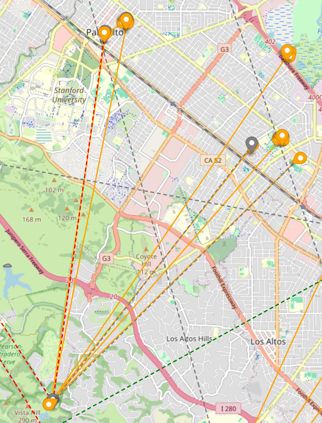
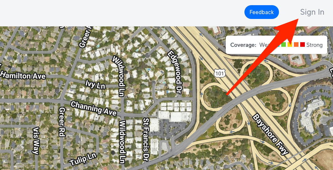
Once you have selected one or several potential mid-tier sites, you can estimate the actual characteristics of the path, including obstructions, using a path planning tool provided by Ubiquiti, called the UISP Design Center. Click the button below to open the UISP design center on an example project that uses Channing House as the mid-tier site. Click on SIgn In, create an account, and then save the example project.
Click on the summary block at the bottom of the page. This will open a detailed view of the link.

The detail looks like this. On the left side are the specifics for Channing House. The latitude, longitude, height, power, bandwidth (10 MHz), radio type (Rocket5AC Lite) and antenna (dish) have also been set for you. The right side is for your QTH. The radio, antenna and power have been set. You should change the Name to your address and set the height (above terrain) where your antenna will sit. It is unlikely you will have your antenna at 89 ft. as shown! On the map, drag the handle for this end of the link to your QTH. The latitude and longitude will update automatically. Be careful to not drag the Channing side of the link. Save the project.
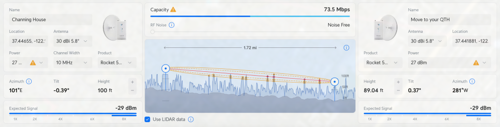
The graph in the center shows the path with roughly-correct terrain / vegetation data derived from LIDAR. Experience has shown that this should be taken only as a guideline, with visual verification and possibly a test with a real node and antenna are strongly recmmended. Generally, the LIDAR data is fairly accurate for terrain but not so much so for vegetation.
In the example shown, the Fresnel Zone is partially obstructed in several places -- note where the trees push into the ellipse. Keep in mind that this is only a 2-D analysis and the actual blockage of the Fresnel Zone is a 3-D thing. Based on what is shown here, this path may not perform well. The choice of antenna will make a huge difference. The analysis shown is based on a 30 dBi dish and may actually work. If you switched to a 10dBi vertical, there would be little hope.
If the path you have chosen is obstructed like this one is, try analyzing the path to a different mid-tier node. You can add multiple PtP links on a single map and experiment with them. Antenna height is very important. Consider the possibility of elevating your antenna. In the flat parts of Palo Alto, this is often required to get past the trees. Once you have settled on a path, make a note of the channel and mode from the table above. You will need these to set up your equipment.
Don't forget to save your work.
Acquiring equipment
At the time of this writing, the best choice of equipment is the Ubiquiti Rocket 5AC Lite and one of the compatible antennas. This will maximize compatibility with the mid-tier nodes in the Palo Alto network.
- Rocket 5AC Lite
- Compatible antenna
The Rocket 5AC Lite comes with a PoE power injector. If you are only connecting a single laptop via ethernet and you are not interested in creating a WiFi hotspot, this equipment should suffice. A more flexible setup includes a PoE network switch and a PoE-powered WiFi access point:
A word about Power over Ethernet (PoE)
You will see many devices that claim to be 'PoE' but beware. There are many different and incompatible versions of PoE.
Ubiquiti equipment uses so-called passive PoE, a 24-27 volt system that lacks intelligence to negotiate the PoE connection. The more advanced PoE+ and PoE++ are not compatible with Ubiquiti PoE. The safest approach is to use all-Ubiquiti radios and switches based on passive PoE and to pay attention to the difference between passive PoE and the other varieties.
More details are available on Ubiquiti's site.
Configuring your radio for AREDN
You will need a laptop, a network switch, and a PoE injector set up in this configuration. If your switch has passive PoE capability, enable it for the radio's connection and forget about the PoE injector.
If you have taken the advice to stick with Ubiquiti Rocket 5AC Lite, there is a nice set of instructions for how to install the AREDN firmware here. Follow them carefully.
Once you have installed the AREDN firmware, you will be able to use the node's web UI to
- Set the latitude and longitude
- Set the channel and bandwidth (per the table above)
- Set the mode (per the table above)
- Test the signal strength and tweak the antenna aim to maximize it.
A good overview of the web UI is found here.
Installing your radio and antenna
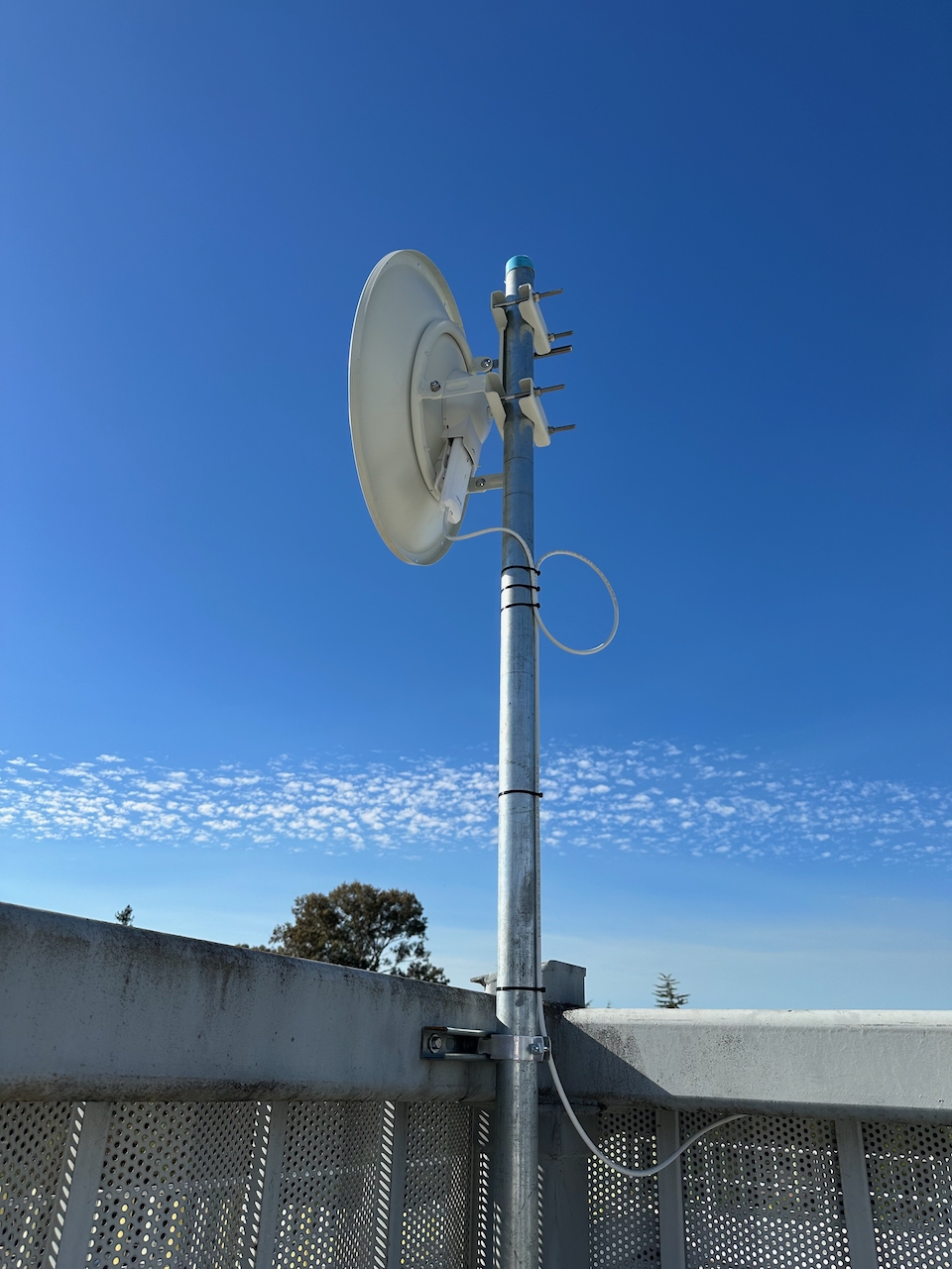
Installing your antenna and radio requires some attention to how the antenna will behave under wind loading. A dish antenna, in particular, will put stress on any mechanical mount in high winds, and you are advised to plan accordingly. Our experience with dish antennas for the Palo Alto AREDN network have led us to choose 2" galvanized steel pipe (NOT thinwall EMT) that is securely attached to something that can handle the torsion caused by wind loading. Home Depot has all the supplies you will need.
The photo to the right shows one of the Palo Alto AREDN dishes mounted on 2" galvanized steel pipe and attached to a steel fence using Unistrut and pipe clamps. While only one mounting point is shown, there are actually three, providing a strong and secure anchor for the antenna.
Generally, the higher the gain of the antenna you choose, the higher the wind loading and the more attention you will need to pay to safe mounting. There are plenty of resources in the radio literature to help you. You can reduce wind loading with a lower-gain antenna such as an omni, but the loss of gain (e.g., 30 dBi for a dish, 10 dBi for an omni) may be the difference between a good AREDN connection and no AREDN connection.
Example wind load calculation
Wind load calculations are covered in the antenna literature for amateur radio operators. The ARRL has a number of resources, and we recommend you become familiar with the subject. Your situation will be unique to your location and the safety factors you choose. This is an example calculation of wind load, but please don't take it as authoritative. You must do your own calculations.
- Establish your antenna's wind load design point: pick an antenna and consult its datasheet to understand the wind loading. Sometimes the datasheet will give a specific wind loading at a specific wind speed. As an example, Ubiquiti's 30 dBi dish will create a 176 pound force at 125 mph, (not counting the wind load of the mounting pipe itself) which happens to be the antenna's stated survivability limit. Sometimes the datasheet gives the effective cross-sectional surface area of the antenna instead of a specific wind load. From the area, you can compute wind loading at any wind speed you choose. An online wind load calculator that does this is available here.
Would Ubiquiti's assumed wind speed of 125 mph be adequate? You will have to decide that for yourself. You can consult wind history for Palo Alto to make a determination. In 2023, the Mercury News reported peak wind speed in Palo Alto at 68 mph. Naturally, that's not any kind of a guarantee any more than a 'high water mark' in a flood zone. You will have to pick a wind speed limit with which you are comfortable. - Pick a mounting type and select a safety factor: You might choose threaded, galvanized Schedule 40 steel pipe of 2" diameter. It will have material properties that determine how much load (force) can be applied without creating permanent deformation. In addition, it is common to choose a safety margin that essentially de-rates these material properties. In our example, we might choose a 2x safety margin, essentially meaning that you will calculate pipe bending based on a wind load twice as high as the actual value. Viewed another way, you can assume the pipe has half the strength the data sheet says.
The bending force on the pipe will also depend on the distance between the antenna itself and the mounting point of the pipe. You should assume all the force is concentrated on the pipe at this distance. For example, using a 10' pipe, you might have the antenna attached 5' above the highest mounting point of the pipe. - Compute the bending limit: With the choice of antenna, wind speed, safety margin, mounting type (e.g., pipe) and mounting distance, you can compute the bending limit via an online calculator, or you can consult pre-computed tables that match your design choices. For example, Alvin Industrial's loading chart for 2" Schedule 40 steel pipe reports that the max load for 5' of pipe is 2149 pounds assuming a 2:1 safety factor when the load is evenly distributed. But in our case, the load is at a point. Alvin reports the requirement to de-rate the maximum load in the case of a load concentrated at a point. For our 5' example, the de-rating factor is 0.083. This gives a maximum loading for the pipe of 178 pounds (2149 times 0.083). This loading is in line with our assumptions.
Your actual case will vary from this example.
Maximum permissible RF exposure
As an amateur radio operator, you are required by the FCC to perform a maximum permissible exposure (MPE) calculation. MPE determines a so-called minimum compliance distance, meaning that your antenna should be at least this far from people.
An online calculator is available from ARRL here.
As an example, you could assume the following parameters:
- Power at the antenna: 0.5 watts (27 dBm -- the actual value will be what you choose in the AREDN user interface)
- Mode duty cycle: 100%
- Tx/Rx timing: 5 minutes transmitting, 10 minutes receiving
- Antenna gain: 30 dBi (using the Ubiquiti dish as an example, at its main lobe -- sector and vertical antennas will have lower gain)
- Operating frequency: 5800 MHz (the actual value will be determined by the channel you choose in the AREDN user interface)
ARRL's calculator reports a minimum compliance distance of 6 feet for an uncontrolled environment. But this is a worst-case scenario because we started with the stated gain of the antenna. That would only be the case if the people in question were standing in front of the antenna which is not likely to be the case for an antenna mounted on a roof and pointing at a mid-tier site. MPE for humans behind or under the antenna will be much lower because the antenna's gain off-axis is significantly reduced. For example, the MPE uncontrolled-environment minimum compliance distance for a 10 dBi sidelobe of the antenna is less than 6 inches.
Connected, finally
Now that your radio is configured, your antenna is mounted, and you've connected up your endpoint equipment, you should be on the AREDN network.
Now is a good time to read the rest of the docs, found here.